
3 MW Marine Fuel-Cell Hybrid Powertrain
The 3 MW marine fuel-cell hybrid powertrain project (2023), led by the author, connected vessel requirements and system architecture to MATLAB/Simulink component models and a central rule-based energy management strategy, and compared battery sizing and dispatch policies over two vessel duty cycles.
Matching a Hybrid Powertrain to a Day at Sea
Offshore vessels alternate between high-power transit, manoeuvring, intermittent work and idle periods. In a fuel-cell and battery hybrid powertrain, the fuel cells supply steady power efficiently while the batteries cover periods when the fuel cells are off and parts of the demand assigned to them. The powertrain must meet the full duty cycle, including onboard auxiliary loads, and the heat generated by the fuel cells becomes a design load in its own right. Battery size, dispatch policy and thermal management therefore have to be assessed together against realistic working days.
Modelling Workflow and Dispatch Rule
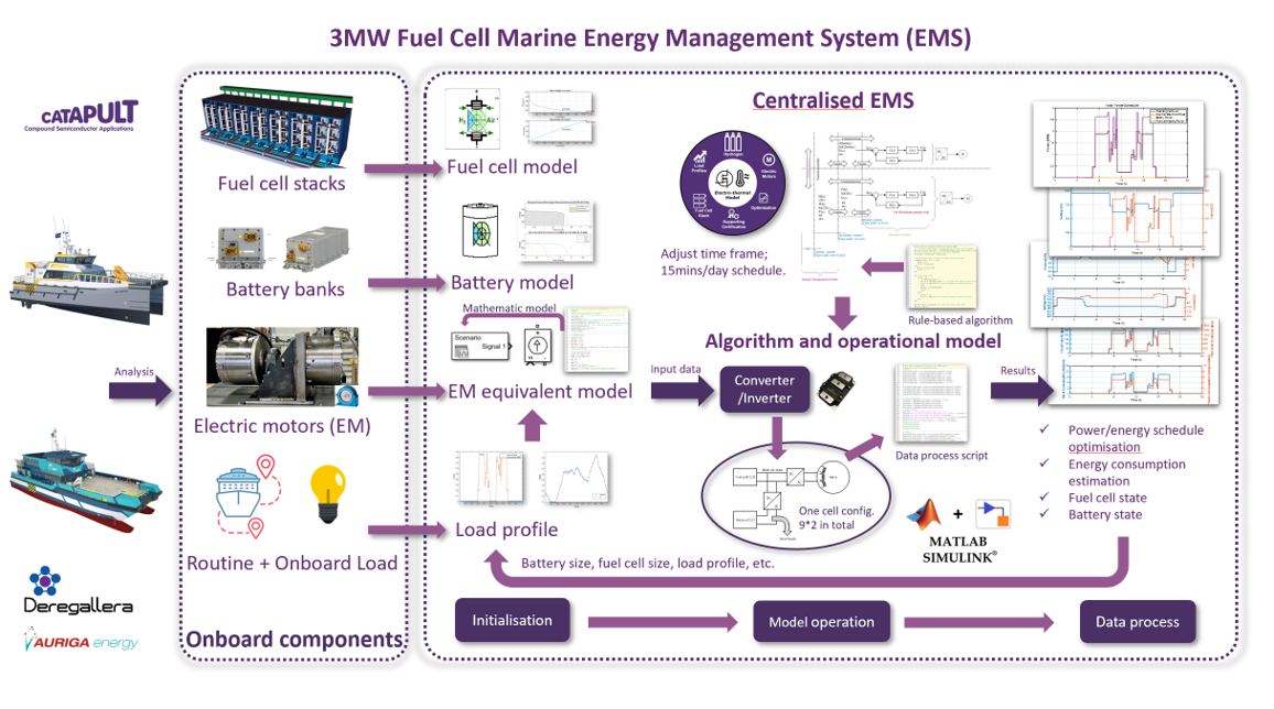
The released model represents two propulsion engines with nine cabinets per engine and five fuel cells per cabinet. A central rule-based controller activates the fuel-cell and battery models against time-varying propulsion and auxiliary demand: fuel cells supply demand while on, and batteries take the assigned demand while the fuel cells are off. Simplified converter representations serve this system-level study.
The scheduling study uses 15-minute intervals over a 24-hour day, starting at 80% battery state of charge. Two duty cycles, HST and BMT, represent different working days, with the project’s 110 kWh HST and 280 kWh BMT battery cases under the revised dispatch rule. Outputs include component voltage and current, battery state of charge, and fuel-cell efficiency, reactant flow and generated heat.
Simulation Results
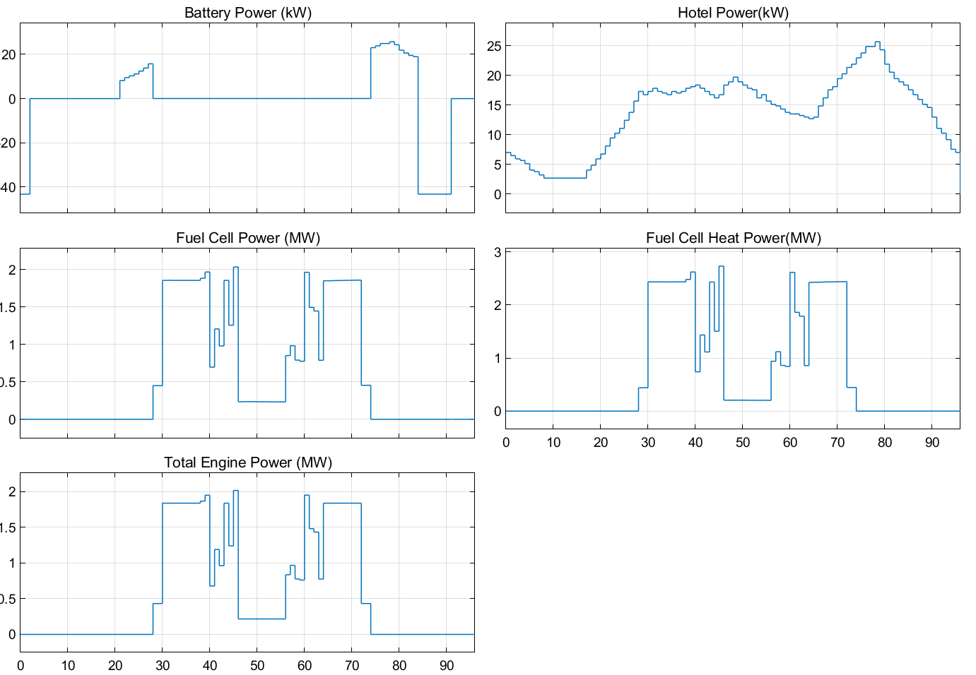
On the HST working day, Case 2 uses 13.721 MWh of fuel-cell electrical energy and generates 17.188 MWh of heat. Across the minimum and maximum HST cases, electrical energy ranges from 10.704 to 17.190 MWh and heat generation from 12.968 to 22.623 MWh.
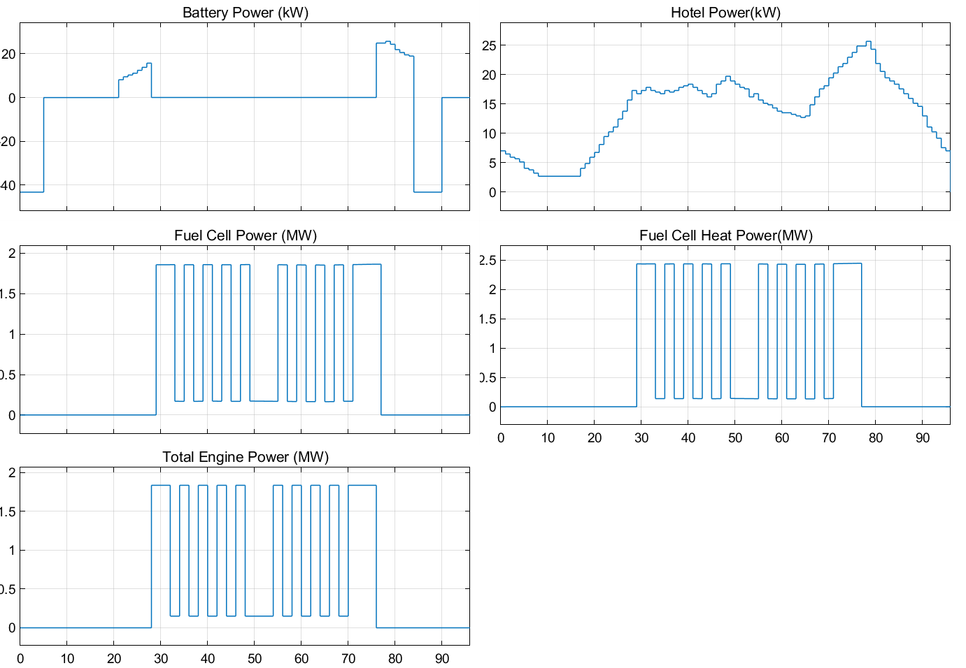
The BMT day, with repeated offshore demand changes, produces a different fuel-cell and battery operating pattern, using 13.007 MWh of fuel-cell electrical energy and generating 16.603 MWh of heat.
Design Implications
The study showed that battery sizing depends on the dispatch policy: assigning electric manoeuvring and auxiliary loads to the batteries creates a different energy requirement from reserving them for fuel-cell-off periods. In each reported case, the fuel cells’ generated heat over the day exceeds their electrical output, making thermal management a primary design consideration alongside electrical dispatch. All results are simulations under the documented dispatch rule and assumed auxiliary-load profile.
The project delivered a reusable workflow for comparing duty cycles, battery allocations and operating rules, and provided the heat-load context for the subsequent thermal evaluation.