
AIPE Sketcher
AIPE Sketcher is the schematic agent in the AIPE framework. It turns a circuit description into a clean SVG schematic drawn with a standard symbol library, then reads the connections back from the drawn wires to prove that the drawing matches the circuit. This page explains the framework it belongs to, its role there, how the agent is organised, and a dual-active-bridge schematic it has drawn.
The AIPE Framework
AIPE (AI for Power Engineering) is the open engineering ecosystem I am building through AIPE Labs. It treats power-converter design as a coordinated, iterative optimisation process rather than a chain of separate tools. Specialist agents each own one engineering step: electrical sizing, schematic drawing, circuit simulation, device and magnetics selection, thermal and field analysis, mechanical CAD and PCB layout. They exchange explicit inputs, assumptions, results and evidence through a shared Engineering State.
A workflow engine runs these steps as a checkpointed task graph. Results from later stages, such as magnetics or finite-element parameters, feed back into the circuit model, and every result is recorded against a verification gate. Software checks do not replace engineering review, measurement or hardware qualification, which remain separate gates. The first full benchmark is a 10 kW dual-active-bridge converter (800 V → 400 V, 100 kHz).
Role of the Sketcher
The Sketcher works alongside the electrical design stage. Once a converter’s topology and connections are defined, it draws them as a schematic that engineers can read, review and include in design documents. It draws the circuit it is given: it does not choose the topology or size any component.
| Interface | Content |
|---|---|
| Inputs | A plain-language request to an AI agent, a named reference converter, explicit Circuit IR JSON, or an Engineering State carrying the circuit with its evidence references |
| Outputs | An SVG schematic, a JSON report of electrical validation, drawing connectivity and layout quality, and a provenance file with hashes of the circuit and drawing |
| Hand-off | Schematics and their reports go into design documents and review packages; in AIPE mode the provenance file links each drawing to the state it came from |
The Sketcher runs on its own as a Codex or Claude Code plugin or a command-line tool, and can read its circuit from the shared Engineering State; it is not yet a task in the DAB workflow. Connectivity validation shows that the drawing matches the circuit, not that the circuit is correct, safe or well rated. The agent interface defines these inputs, outputs and limits. The code is source-available for personal, non-commercial use.
How the Agent Is Organised
The agent treats the circuit, not the drawing, as the source of truth. An electrical description called Circuit IR records every component, port and net. The drawing is built from that description in stages, and nothing after the Circuit IR may change a connection.
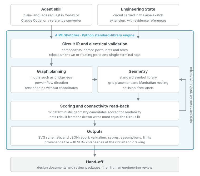
| Part | Responsibility |
|---|---|
| Agent skill | Turns a plain-language request or a named reference converter into Circuit IR. Codex and Claude Code load the same skill and the same drawing engine. |
| Circuit IR and electrical validation | Records components, named ports, nets and roles; rejects unknown ports, floating ports and single-terminal nets before any geometry exists. |
| Graph planning | Recognises motifs such as bridge legs, infers the power-flow direction and describes the layout as relationships, without coordinates or converter names. |
| Geometry | Maps components to symbols from the standard library, places them on a grid, routes Manhattan wires and places labels without collisions. |
| Scoring and connectivity read-back | Builds and scores 12 deterministic geometry candidates, then rebuilds the nets from the drawn wires alone. Crossing wires never join, and any mismatch rejects the candidate. |
| Outputs | Write the SVG, a JSON report with scores, warnings, assumptions and limits, and in AIPE mode a provenance file with SHA-256 hashes. |
The planner never sees a converter’s name, so the same rules draw a buck converter, a dual active bridge or a synthetic test network. The architecture and known limits and layout rules describe these stages in detail.
Example: Dual-Active-Bridge Schematic
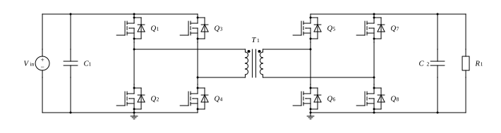
This example draws the topology of the AIPE benchmark converter, a dual active bridge. The recorded run started from a plain-language request in Codex: “Using AIPE Sketcher, draw a Dual Active Bridge converter schematic and export it as SVG.”
From Request to Schematic
- Circuit IR. The skill loaded the reference DAB circuit and wrote it as Circuit IR: 23 components and 16 nets, covering the input source and capacitor, two full bridges of eight switches, the transformer, and the output capacitor and load.
- Electrical validation. Every port belonged to exactly one net, with no floating ports or single-terminal nets.
- Planning and geometry. The planner recognised the bridge legs on each side of the transformer, then built and scored 12 geometry candidates.
- Read-back and report. The selected candidate’s drawn wires reproduced the Circuit IR exactly, and the agent wrote the SVG and its report.
Validation Report
| Check | Result |
|---|---|
| Electrical validation | Passed, no problems |
| Drawing connectivity read back from the wires | Passed, no faults |
| Layout score | 97 / 100, candidate 3 of 12 selected |
| Layout warnings | Two wire runs (nets PRI_B and SEC_A) slightly longer than the preferred spacing band |
| Repeatability | Byte-identical SVG from the Codex agent run, the engine installed with the Claude Code plugin and the repository command line |
The same rules draw the repository’s other reference and synthetic circuits, from a buck converter to an LLC resonant converter and a three-phase inverter. Their layout scores range from 96 to 100, and every one passes the connectivity read-back. The regression results list all 14 circuits.
Task Outputs
The task produced the Circuit IR file, the SVG schematic and its JSON report. The reference circuit is an illustrative topology, not the 10 kW design: its stated assumptions place the energy-transfer inductance inside the transformer rather than as a separate inductor, and it carries no component values or ratings. Connectivity validation proves the drawing is faithful to the circuit; device sizing, losses and performance belong to the other AIPE stages.