
AIPE CAD Agent
AIPE CAD Agent is the mechanical-geometry agent in the AIPE framework. It turns parameter files into FreeCAD models of converter transformers, heat sinks, cold plates and complete assemblies, then checks those models for interference, fit and electrical clearance. This page explains the framework it belongs to, its role there, how the agent is organised, and the 10 kW DAB converter it has modelled.
The AIPE Framework
AIPE (AI for Power Engineering) is the open engineering ecosystem I am building through AIPE Labs. It treats power-converter design as a coordinated, iterative optimisation process rather than a chain of separate tools. Specialist agents each own one engineering step: electrical sizing, schematic drawing, circuit simulation, device and magnetics selection, thermal and field analysis, mechanical CAD and PCB layout. They exchange explicit inputs, assumptions, results and evidence through a shared Engineering State.
A workflow engine runs these steps as a checkpointed task graph. Results from later stages, such as magnetics or finite-element parameters, feed back into the circuit model, and every result is recorded against a verification gate. Software checks do not replace engineering review, measurement or hardware qualification, which remain separate gates. The first full benchmark is a 10 kW dual-active-bridge converter (800 V → 400 V, 100 kHz).
Role of the CAD Agent
CAD Agent works at the physical-design stage, alongside the PCB Agent. It receives the decisions of the magnetics and thermal stages, such as the selected core, winding layout and heat-sink geometry, and turns them into solid models that show how the parts fit together. The models support layout, mass, interference and clearance studies, and give simulation tools geometry to mesh.
| Interface | Content |
|---|---|
| Inputs | JSON parameter files in SI units for a transformer, heat sink, cold plate or assembly; in a workflow run, AIPE-Workflows derives them from the selected magnetics candidate, core record and heat-sink candidate |
| Outputs | Editable FreeCAD documents and STEP files, per-body volume and mass metadata, mesh hints and geometric check reports |
| Hand-off | AIPE-Workflows records the models and their check summary under its CAD/PCB gate; open clearance items go to human engineering review |
The models are illustrative geometry, not manufacturable designs. Required clearance and creepage distances are caller inputs, and no compliance with a standard is claimed. The agent interface defines these inputs, outputs and limits.
How the Agent Is Organised
The agent separates the engineering rules from the CAD kernel. A pure-Python resolver validates each parameter file and applies the derived-geometry rules, so the same rules can be used by tests or an optimiser without FreeCAD. FreeCAD then runs headless to build the solids, measure them and check them.
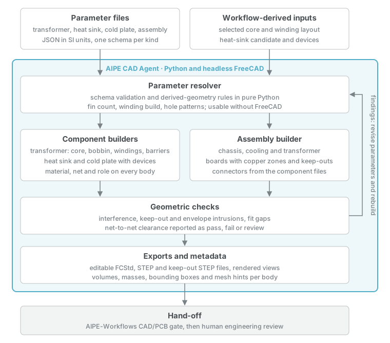
| Part | Responsibility |
|---|---|
| Parameter files | One JSON file per model kind, with a JSON Schema; lengths in metres and masses in kilograms. An assembly file references the component files. |
| Parameter resolver | Validates the inputs and applies derived-geometry rules, such as fin count from pitch, winding build from wire data and hole patterns from device footprints. |
| Component builders | Build transformers (core, bobbin, windings, barriers, pins and clips), plate-fin heat sinks and liquid cold plates with their devices and mounting hardware. |
| Assembly builder | Places the chassis, cooling, boards with copper zones and keep-outs, transformer and connectors from the component files. |
| Geometric checks | Report interference volumes, keep-out and envelope intrusions, fit gaps and net-to-net clearance as pass, fail or review. |
| Exports and metadata | Write FCStd and STEP files with volumes, masses, bounding boxes, mesh hints and rendered views, and re-import each STEP file to confirm its volumes. |
Every body carries its material, electrical net and role, so the clearance check knows which conductors belong to which net. Conductors separated only by solid insulation, such as windings behind a barrier, are reported for review rather than passed, because creepage along surfaces is not traced. The outputs and checks and parameter rules describe these stages in detail.
Example: 10 kW DAB Converter
This example models the mechanical parts of the AIPE benchmark converter: a 10 kW dual-active-bridge converter from 800 V to 400 V at 100 kHz. One command builds all four models from their parameter files with FreeCAD 1.1.4.
| Model | Geometry | Mass | Check outcome |
|---|---|---|---|
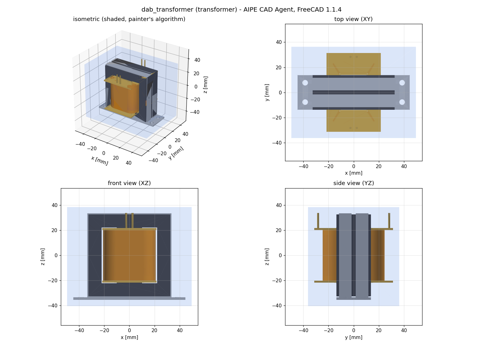
| Transformer | E65/32/27 N87 core pair, 21 : 10 turns (litz primary, foil secondary), 0.5 mm polyimide barrier | 708.6 g | No interference; primary and secondary to earth pass at 15.85 mm; primary to secondary for review |
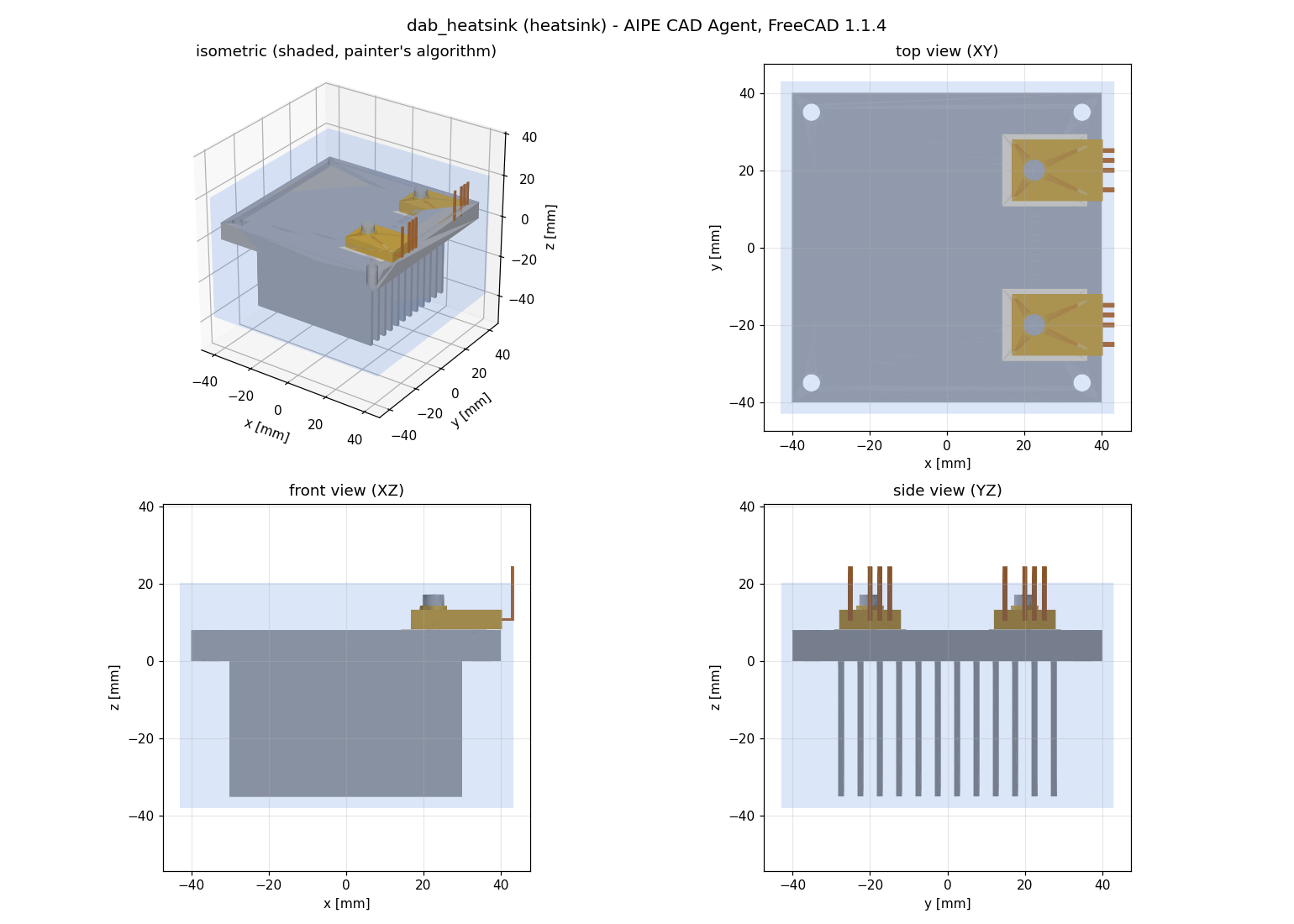
| Heat sink | 80 × 80 mm aluminium base, 12 fins, two TO-247-4L devices on alumina pads | 254.6 g | No interference; device tab to mounting screw for review |
| Cold plate | 240 × 120 mm aluminium plate, four-pass serpentine channel, eight devices | 1184.0 g | No interference; device rows 36.53 mm apart pass |
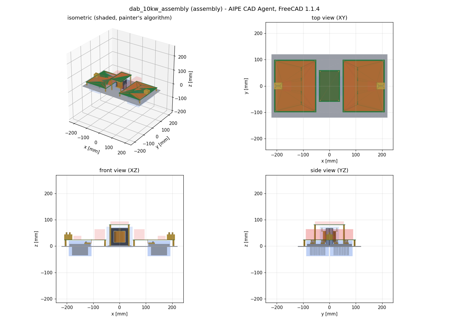
| Assembly | 440 × 240 mm chassis, four heat sinks, primary, secondary and control boards, transformer and terminals | 2.789 kg | No interference or keep-out violations; transformer to control board passes at 10.83 mm |
Transformer
The transformer model builds the core, bobbin, homogenised winding sections sized from the wire data, the insulation barrier, pins, clips and base plate. The windings are separated only by the barrier and bobbin, with no air path between them, so the primary-to-secondary clearance stays an open review item.
Heat Sink
The heat-sink model mounts two TO-247-4L SiC devices on isolation pads with shoulder bushings and screws. The pitch rule alone would give 16 fins; the parameters use 12 shorter fins, which leave a rim for the chassis.
Converter Assembly
The assembly places the primary and secondary power boards on standoffs above four heat sinks, the transformer between them and the control board above it. Board keep-outs reserve space for the DC-link capacitors and gate drivers.
Within the Workflow Run
In the AIPE-Workflows DAB run, the transformer and heat sink were built from upstream results rather than hand-written parameters. The transformer used the E70/33/32 core and winding layout chosen by the magnetics stage; its CAD mass of 0.864 kg compares with the magnetics estimate of 0.696 kg, the difference being mainly bobbin, barriers, clips and plate. The heat sink used the thermal stage’s selected candidate; the CAD mass of the sink body, 0.275 kg, was 1.3 % below the thermal correlation model’s 0.278 kg.
Task Outputs
Each model produces an editable FreeCAD document, a STEP file, a keep-out STEP file, a metadata file and a check report. STEP re-import reproduced every solid’s volume. The open review items are real: the transformer’s inter-winding insulation has not yet been designed, and no part has been manufactured or measured.