
Passive Control for Boost Converter
This PhD work developed a passive stabiliser for Boost interface converters in DC microgrids. Derived from an averaged converter model, it adds a high-pass-filtered feedforward path that suppresses oscillation without shifting the steady-state bus voltage.
Passivity and Boost Converter Stability
The target is the Boost interface converter that connects a distributed source, such as a battery or PV array, to the common DC bus. Its switches step the source voltage up to the bus voltage, and its output capacitor and the bus loads form the terminal it must keep stable.
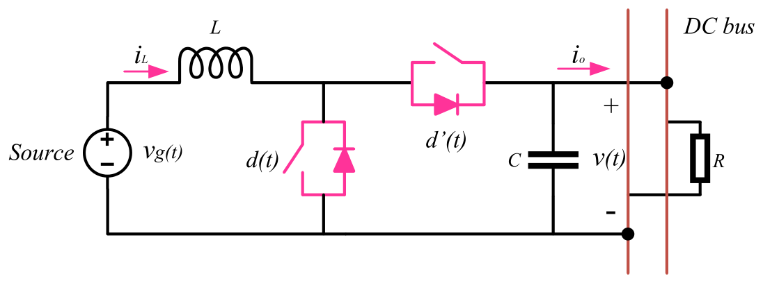
A Boost converter’s voltage-control plant contains a right-half-plane zero: a change in duty cycle first drives the output voltage in the opposite direction to its final response. This non-minimum-phase behaviour constrains the voltage-loop design and, in a DC microgrid with several interacting converters, can contribute to instability.
Passivity offers a design criterion that holds as systems are connected together. A passive system cannot deliver more energy than it receives plus its initially stored energy. For input u, output y, stored energy H and dissipated energy ε, the energy balance is:
For a stable linear time-invariant, single-input single-output system, passivity corresponds to a positive-real transfer function:
The design therefore asks where the Boost converter’s outer-loop plant fails this condition, and how to correct it.
Designing the Passive Stabiliser
Averaged Model and Outer-Loop Plant
Neglecting small parasitic resistances, the averaged inductor-current and output-voltage equations are:
where vg is the source voltage, iL the inductor current, v the DC-bus voltage, io the output current and d the duty ratio. Applying small variations around an operating point gives the equivalent small-signal model:
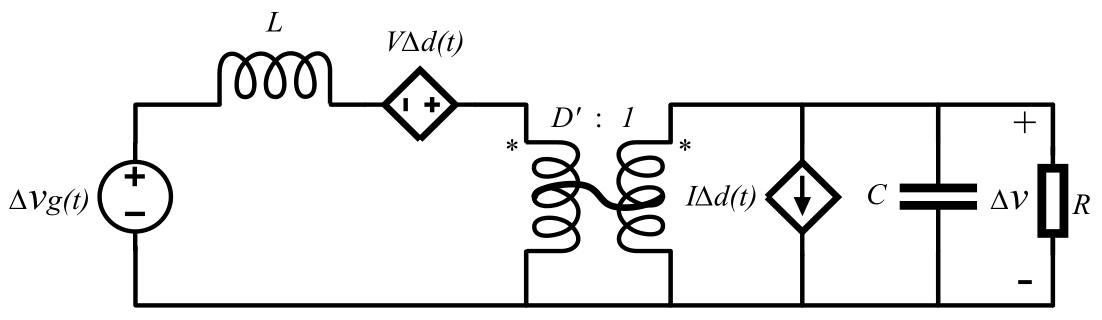
From this model follow the duty-to-voltage and duty-to-current transfer functions:
With the inner current loop following its reference closely, the common denominator cancels, giving the approximate outer-loop plant from current reference to bus voltage:
where Rf is the current-sampling gain, R the equivalent load resistance and D′ the steady-state complementary duty ratio. The numerator zero lies in the right half-plane.
Where the Plant Loses Passivity
The real part of the plant response is:
It becomes negative above a crossing frequency and tends to a negative high-frequency limit:
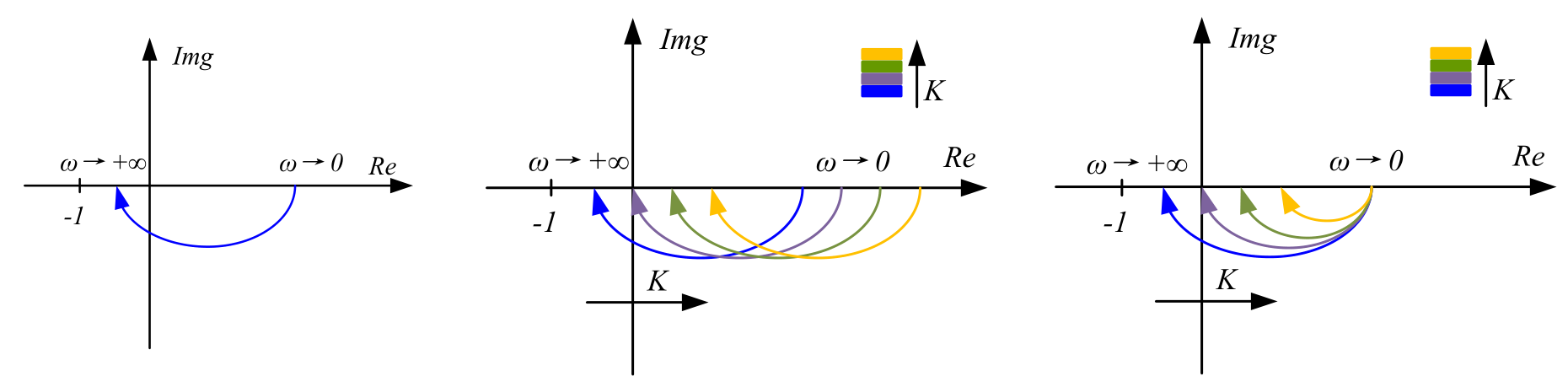
Constant Feedforward
Adding a parallel feedforward gain K shifts the plant towards the positive-real region:
A gain at least as large as the negative asymptote offsets it, but the same gain changes the DC value from α to α + K and so shifts the steady-state bus voltage. This motivates a feedforward path that is suppressed at low frequency.
Filtered Passive Stabiliser
A first-order high-pass filter keeps the high-frequency compensation while its DC gain tends to zero:
The gain compensates the high-frequency deficit, and the filter corner sits below the frequency at which the uncompensated plant loses passivity:
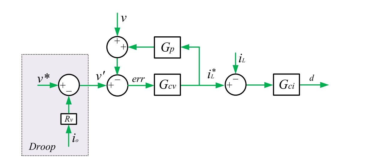
In the control structure, the current controller regulates the inductor current and the voltage controller supplies its reference; droop control adjusts the voltage reference for power sharing, and the stabiliser shapes the outer-loop dynamics in parallel. The current controller, voltage controller and stabiliser were discretised with a bilinear approximation for implementation on the converter’s DSP. The gain, filter corner and terminal capacitance are chosen for the analysed converter and its operating point, and must be reviewed for a different operating point or load. The same stabiliser applies to each converter when several Boost interfaces share current through droop control.
Simulation Results
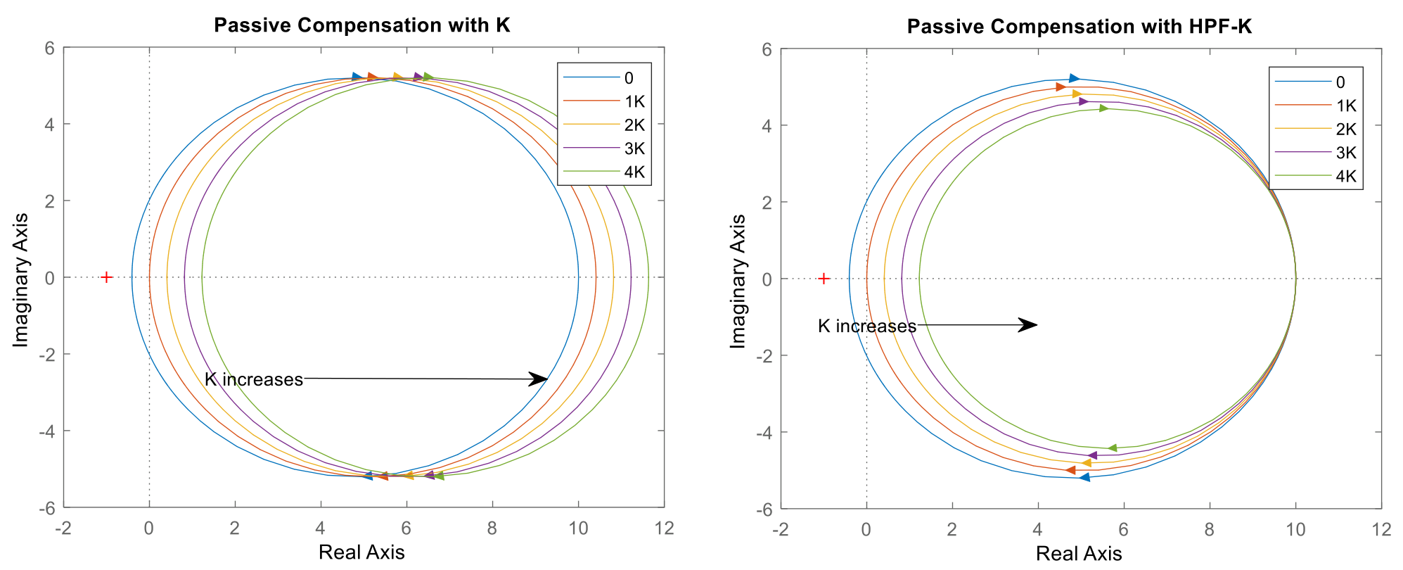
For the thesis example parameters, numerical Nyquist plots confirm the distinction between the two approaches: a constant gain shifts both real-axis endpoints, while the filtered gain leaves the low-frequency endpoint unchanged as the gain increases.
PhD thesis: Control Strategies for Low Voltage DC Microgrids, Chapter 5. · Novel Passive Controller Design for Enhancing Boost Converter Stability in DC Microgrid Applications, IEEE JESTPE, 2021.
DC Microgrid Control Strategies · Dual-Window DC Bus Signalling · Back to Research