
Dual-Window DC Bus Signalling
The dual-window DC bus interacting (DBI) method developed in this work lets sources and storage in a DC microgrid exchange operating commands through the DC bus voltage itself, without a separate communication link. The work covered the design of the voltage windows, signal sequences and converter-control modifications.
Coordinating Converters Through the Bus Voltage
In a DC microgrid, droop control lets several converters share load without communication: each converter lowers its output voltage as its current rises, so the bus voltage itself indicates loading. Higher-level coordination, such as switching a battery on or handing bus regulation from one source to another, normally needs a separate communication network.
Bus signalling removes that network by also using the bus voltage to carry deliberate messages. The difficulty is keeping messages distinct from the ordinary voltage changes caused by droop control.
From Voltage Level Signalling to Bus Interacting
Coordination through the bus has developed in steps. Voltage level signalling schedules each source in its own voltage window: as load rises, a source saturates its inner current loop, the bus voltage falls, and the next window wakes another source. DC bus signalling adds droop within each window, so newly connected sources can share power in an existing window and fewer windows are needed.
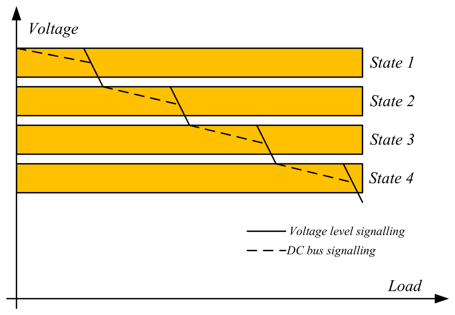
| Method | How sources coordinate | Limitation |
|---|---|---|
| Voltage level signalling | Each source works in its own bus-voltage window, entered as the previous source saturates | Every new source needs a new window |
| DC bus signalling | Droop within each window lets several sources share one state | The load, not the operator, decides the operating state |
| Mode-adaptive DC bus signalling | One converter holds the bus as a voltage source; others switch between voltage-source and current-source modes | Many sources are hard to regulate with voltage states alone |
| Power line communication | Dedicated signals, or modulated switching ripple, carry data along the power lines | Needs modulation and demodulation circuits and signal processing, and can affect power quality |
| Dual-window bus interacting (proposed method) | Deliberate voltage sequences in a signalling window, outside the droop working window | Low data rate, and deliberate voltage excursions |
The DC bus interacting method combines the plug-and-play behaviour of droop control, the accurate power sharing of current-source operation and the voltage signalling of DC bus signalling, without extra links or modulation circuits. Each source alternates between two periods. In the plug period it works as a voltage source with droop, so that it can be registered and exchange signals through the bus; at least one converter, such as the grid interface, always holds the bus voltage. In the play period it works as a current source, so that its power, such as a battery’s charging current, can be set accurately.
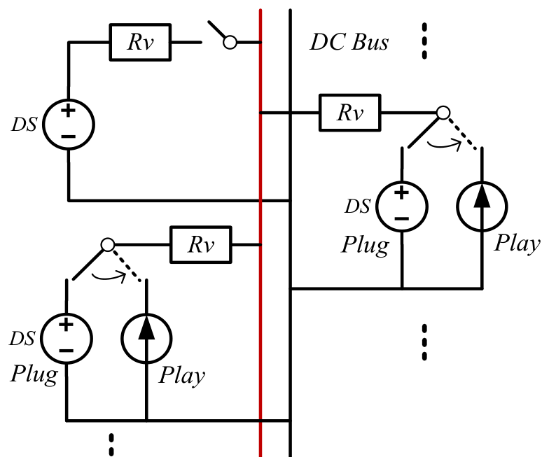
Working and Signalling Voltage Windows
The proposed method separates the two functions into distinct voltage ranges. Normal droop operation stays within a working window, while deliberate signalling uses a level outside it. The design uses a 45–50 V working window and a 52.5 V signalling level.
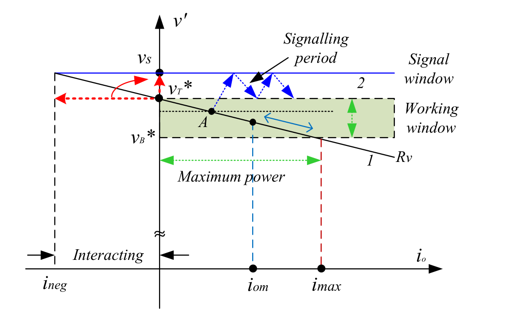
To send a message, one converter temporarily drives the bus voltage through a sequence while the others decode it, then returns to its assigned power-control role. As the bus rises during reception, the receiving converters’ outer voltage loops would otherwise demand unwanted negative current. The method therefore isolates that loop during reception and applies a positive or zero current reference, limiting the extra power the signalling converter must supply. Each converter returns to its normal control mode after the sequence.
System Commands
The simplest messages switch a converter on or off. The integrated system extends the method to six-bit commands at 100 ms per bit, selecting converter identity, operating mode, charging or discharging and current reference.
These commands carry the rule-based EMS: one interface regulates the bus, and explicit signals hand that role to another. Using the bus for both power and information simplifies the communication arrangement, at the cost of low bandwidth, deliberate voltage excursions and settling intervals that must suit the connected loads and the required coordination speed.
A Dual-Window DC Bus Interacting Method for DC Microgrids Hierarchical Control Scheme, IEEE Transactions on Sustainable Energy, 2020. · PhD thesis, Chapters 4 and 6.