
Rule-Based EMS and Hierarchical DC Microgrid Operation
This PhD system study brings passive control, droop coordination and dual-window bus signalling together under a rule-based energy management system (EMS). The study integrates the control layers, defines the operating rules and six-bit signalling scheme, and analyses the terminal admittance.
Who Regulates the Bus?
A DC microgrid must continually decide which converter regulates the bus voltage, when batteries charge or discharge, and what happens when PV generation exceeds demand and storage is full. A rule-based EMS answers these questions with explicit operating rules tied to the system state. Compared with optimisation-based scheduling, it is transparent and simple to implement on the converters’ own controllers.
The Microgrid System
The scheme is designed for a household-scale DC microgrid in which four interface converters share a DC bus held between 45 and 52.5 V. IC1 connects the 220 V AC grid through a rectifier, with a soaking resistor to absorb surplus power; IC2 and IC3 connect two 24 V battery banks; IC4 connects the PV panels with maximum-power-point tracking and power limitation. Electronic and resistive loads draw from the bus.
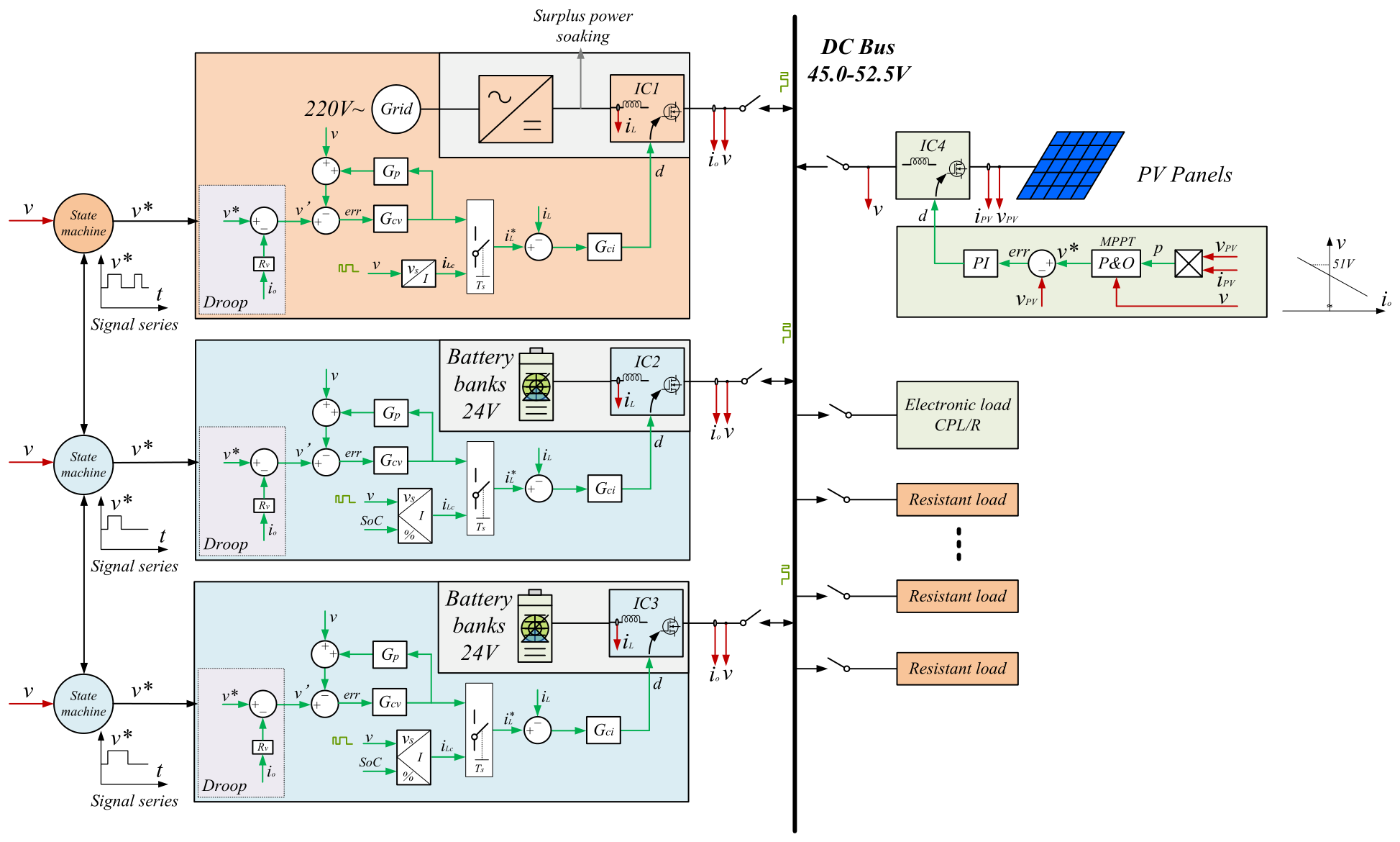
Each grid and battery converter combines the layers of the hierarchy: droop and the passive stabiliser set the voltage reference, voltage and current loops regulate the converter, and a state machine reads the signal series on the bus and sets the converter’s operating role.
Operating Rules and State Machines
Grid-connected operation gives bus regulation to the grid interface; planned disconnection transfers it to a battery. The power-management logic curtails surplus PV near 51 V, distinct from the 52.5 V signalling level. Commands travel through the dual-window bus signalling method as six bits at 100 ms per bit, identifying the start, converter state, battery-interface identity, droop or power mode, charge or discharge state and current selection.
Each converter turns received commands into an operating role through a two-level finite-state machine.
First Level: Sending and Receiving Signals
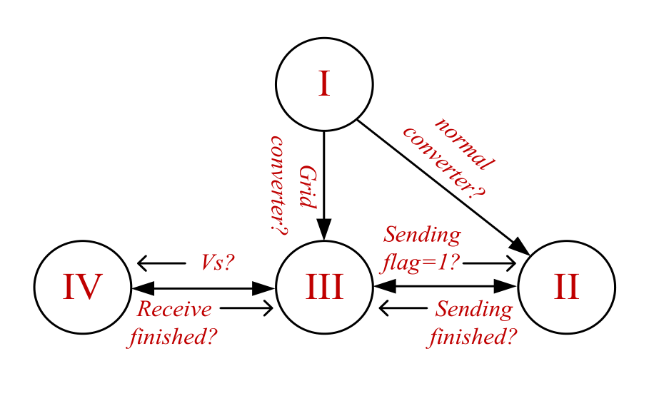
- I — initialisation: determine the interface role. The grid converter enters normal operation directly; another converter first enters the sending state.
- II — sending: transmit the signal sequence, then return to normal operation. Sending can also be triggered during normal operation.
- III — normal operation: monitor the bus, run the operating-mode state machine and initiate signalling when another source needs to be switched.
- IV — receiving: detect and decode a signal, then return to normal operation, applying current compensation while another interface drives the signal.
Second Level: Sleep, Droop and Power Modes
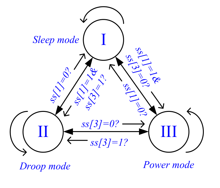
In sleep mode, the interface monitors the bus and waits for a command. An ON command selects droop mode, in which the converter helps regulate the bus, or power mode, in which it follows a commanded charge or discharge current while considering battery state of charge. A change in the mode bit switches between them; an OFF command, or a fully charged battery, returns the interface to sleep. The grid interface starts in droop mode, and other converters start in sleep after their signalling exchange.
The EMS defines rule-based operating sequences for source connection, battery coordination and planned handover of bus regulation, rather than optimal long-term scheduling.
PhD thesis: Control Strategies for Low Voltage DC Microgrids, Chapter 6. · Dual-window signalling paper
DC Microgrid Control Strategies · Energy Management Systems · Back to Research