
Loughborough University DC Microgrid Testbed
A low-voltage DC microgrid test bench was built at Loughborough University around modular interface converters, supporting grid-connected and islanded operation so that converter control and system-level power management can be studied together.
A Modular Test Bench
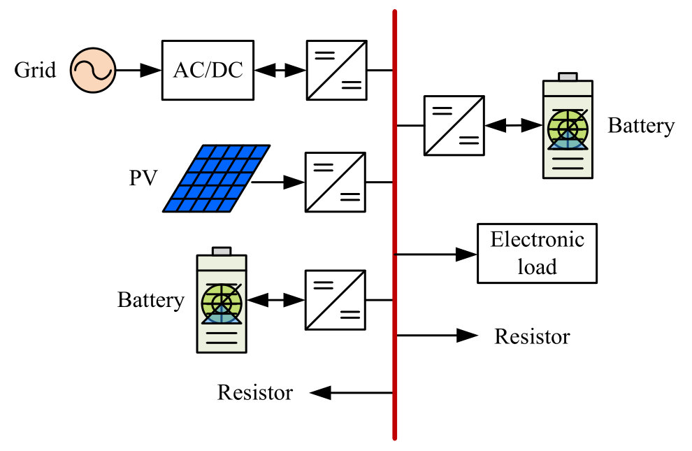
The test bench follows the same four-interface structure as the earlier PhD microgrid: a grid emulator, two battery banks and a PV emulator connect to the DC bus through interface converters, alongside electronic and resistive loads. A DC supply and soaking resistor emulate the grid, and a computer and instruments monitor the system.
Converter Development
The first interface converter was a 100 W bidirectional Boost converter on a 48 V bus. A second version rated at 500 W per converter followed, improving gate drive and sensing, reducing switching ringing and adding wireless communication support. Stacked power and control boards provide voltage and current sensing, gate drive and DSP-based control.
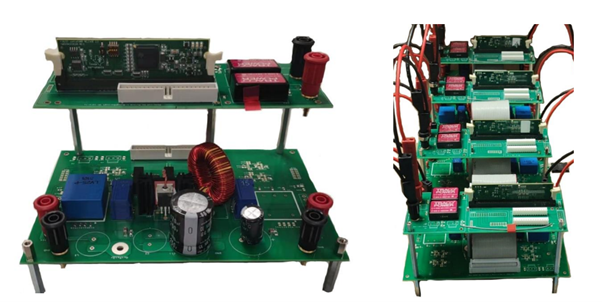
The converters implement current and voltage regulation, battery charging, droop control and PV maximum-power-point tracking.
The Completed Setup
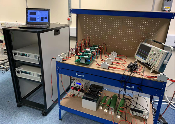
Hardware designs and schematics are available in the DC Microgrid Test Bench repository.
Bidirectional Buck–Boost converter · All experimental platforms · Back to Research