
EMS for DC Microgrids Considering Battery Degradation
Research at the University of Waterloo developed an optimisation-based energy management system (EMS) for DC microgrids that prices battery wear alongside grid electricity. The battery holds the DC bus voltage, and the EMS schedules it so that it is not charged and discharged more than the system needs.
Why Battery Degradation Matters in DC Microgrids
A DC microgrid needs at least one source that regulates its bus voltage. A grid-connected converter can do this while the grid is available, but a battery energy storage system can hold the bus in both grid-connected and islanded operation, which removes the need for a seamless switch between the two modes. Energy management is also simpler than in AC microgrids: with no frequency or reactive power, it reduces to scheduling active power on a two-wire system.
Using the battery this way has a cost. Every charge and discharge cycle wears it, and deep cycles wear it fastest, so an EMS that only minimises electricity cost will cycle the battery heavily and shorten its life. The EMS sits at the top of the hierarchical control scheme, on a time scale of minutes to days, above the converter and bus-voltage control layers.
Degradation Cost Model
For a lead-acid battery, the number of cycles to failure falls steeply as the depth of discharge (DoD) increases, while the total energy throughput over the battery’s life changes little. Deep discharges therefore consume the battery’s life faster for the same energy delivered.
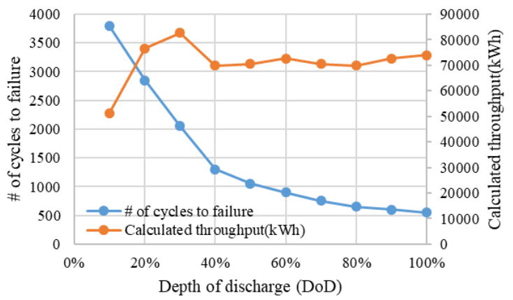
The degradation cost per kWh of throughput divides the replacement cost by the energy the battery can deliver over its life. With battery unit cost Cbu in $/kWh and cycle life ℒb(DoD):
where Pdcbat,t and Pcbat,t are the battery’s discharging and charging power. Any charging or discharging adds to the cost, so reducing it means using the battery less.
EMS Formulation
The battery’s state of charge follows its charging and discharging power, with efficiencies ηc and ηd, and stays between its limits:
Charging and discharging powers are bounded, and neither the battery nor the grid connection may charge and discharge at the same time. With no reactive power, the remaining network constraint is the active power balance on the bus:
where the load Pload,t is the sum of the EV charging, air-conditioning and LED lighting demand.
The objective weighs the cost of grid electricity at price ξdcg,t against the battery degradation cost:
The weighting factor α sets how grid power and battery throughput compete. At α = 1 only the electricity bill counts and the battery is used freely; lowering α gives battery wear more weight, so the schedule leans on the grid and keeps the battery’s state of charge steadier.
Test Microgrid
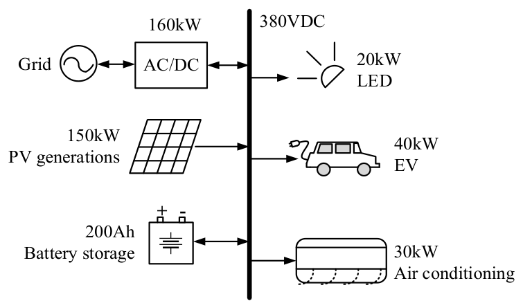
The EMS is formulated for a model of the DC microgrid of a building at Xiamen University. A 380 V DC bus connects PV generation, a lead-acid battery bank that maintains the bus voltage, and a bidirectional AC/DC converter to the grid, with LED lighting, an EV charging station and air conditioning as loads.
| Element | Value |
|---|---|
| Generation and grid | 150 kW PV; 160 kW bidirectional AC/DC grid converter |
| Battery | 200 Ah, 336 V lead-acid bank; ±67.2 kW; replacement cost 200 $/kWh |
| Battery limits | Initial SoC 80%; DoD 60%, so SoC between 40% and 95%; ηc = 95%, ηd = 90% |
| Loads | 20 kW LED lighting, 40 kW EV charging, 30 kW air conditioning |
| Electricity price | 0.077 $/kWh from 8 am to 10 pm, 0.044 $/kWh otherwise |
| Dispatch interval | 15 minutes |
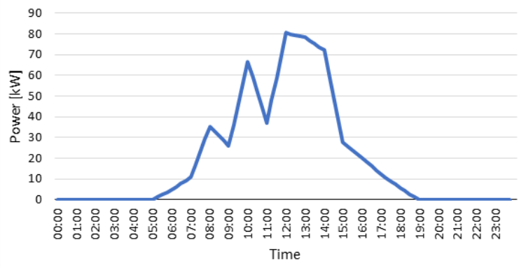
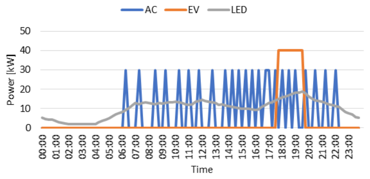
The PV profile represents a summer day, the EV charging station is used after working hours, and the air conditioning cycles intermittently during working hours.
Simulation Results
Solving the EMS for different weighting factors shows how pricing battery wear changes the schedule. As α decreases and the degradation cost carries more weight, the battery’s state of charge flattens out and its charging and discharging power tends to zero, while the battery still holds the DC bus voltage.
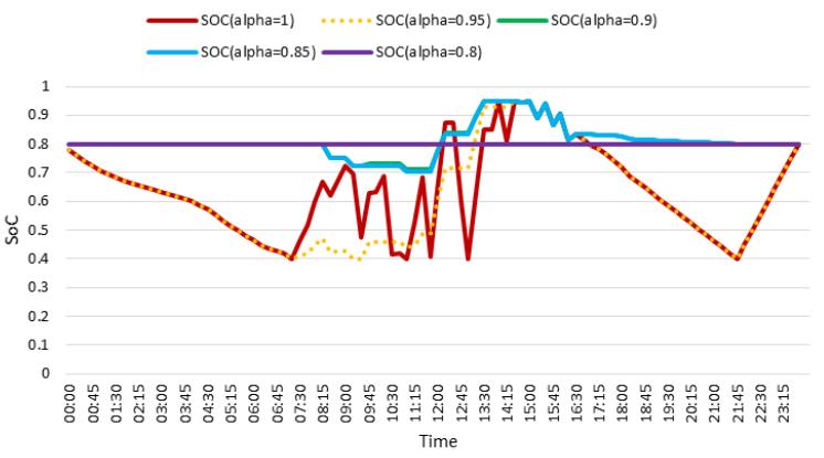
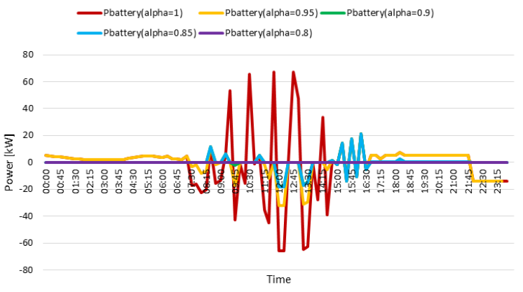
The dispatch for two weightings shows the difference. At α = 0.95, part of the surplus PV around midday charges the battery and the battery supports the evening load. At α = 0.8, the battery is barely used: the grid absorbs the PV surplus and supplies the evening EV and air-conditioning demand, so the battery cycles far less and lasts longer.
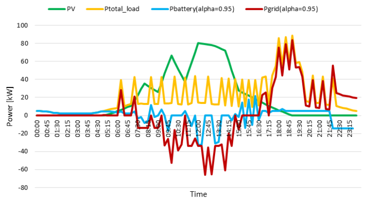
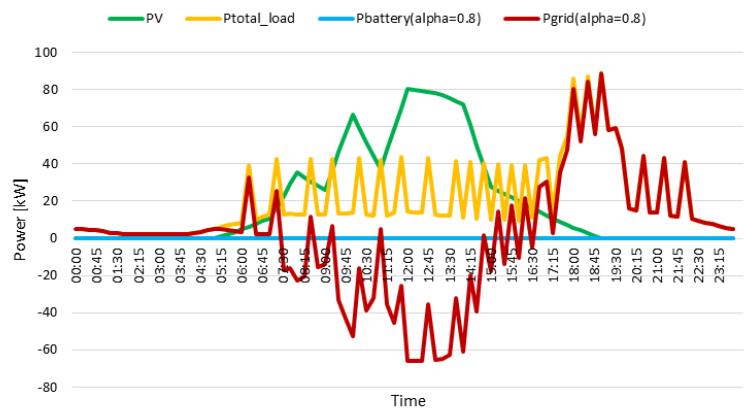
The weighting factor therefore gives the operator a direct handle on how much the battery contributes to the microgrid against how long it lasts. The air-conditioning and EV loads were treated as non-dispatchable; making them controllable is a natural extension of the model.
Energy Management System for DC Microgrids Considering Battery Degradation, IEEE PES General Meeting, 2020 · Accepted manuscript
Microgrid Energy Management · Energy Management Systems · Back to Research