
PCB Rogowski Coil Current Sensing
This work reviewed how the Rogowski coil developed, from its origins to coils built into power modules, and how PCB winding patterns trade off against each other. Building on that review, a family of five PCB coils was designed, each with its own signal-conditioning circuit, for measuring fast current transients in power converters.
How a Rogowski Coil Measures Current
A Rogowski coil is an air-cored winding placed around the conductor carrying the current to be measured. The changing magnetic field of that current induces a voltage in the winding proportional to the rate of change of current:
where M is the mutual inductance between the conductor and the coil. Because there is no magnetic core to saturate, the coil suits large, fast-changing currents such as the switching transients of SiC converters; it does not measure steady DC current.
On a PCB, the winding is formed by traces on the top and bottom layers joined by vias, so each turn has a rectangular cross-section set by the board thickness h and the inner and outer radii a and b. For N evenly spaced turns:
More turns, a thicker board or a wider winding raise the sensitivity. An integrator then recovers a signal proportional to the current, with gain set by its time constant τ:
The integrator’s gain, bandwidth and offset drift therefore matter as much as the coil itself.
Development of the Rogowski Coil
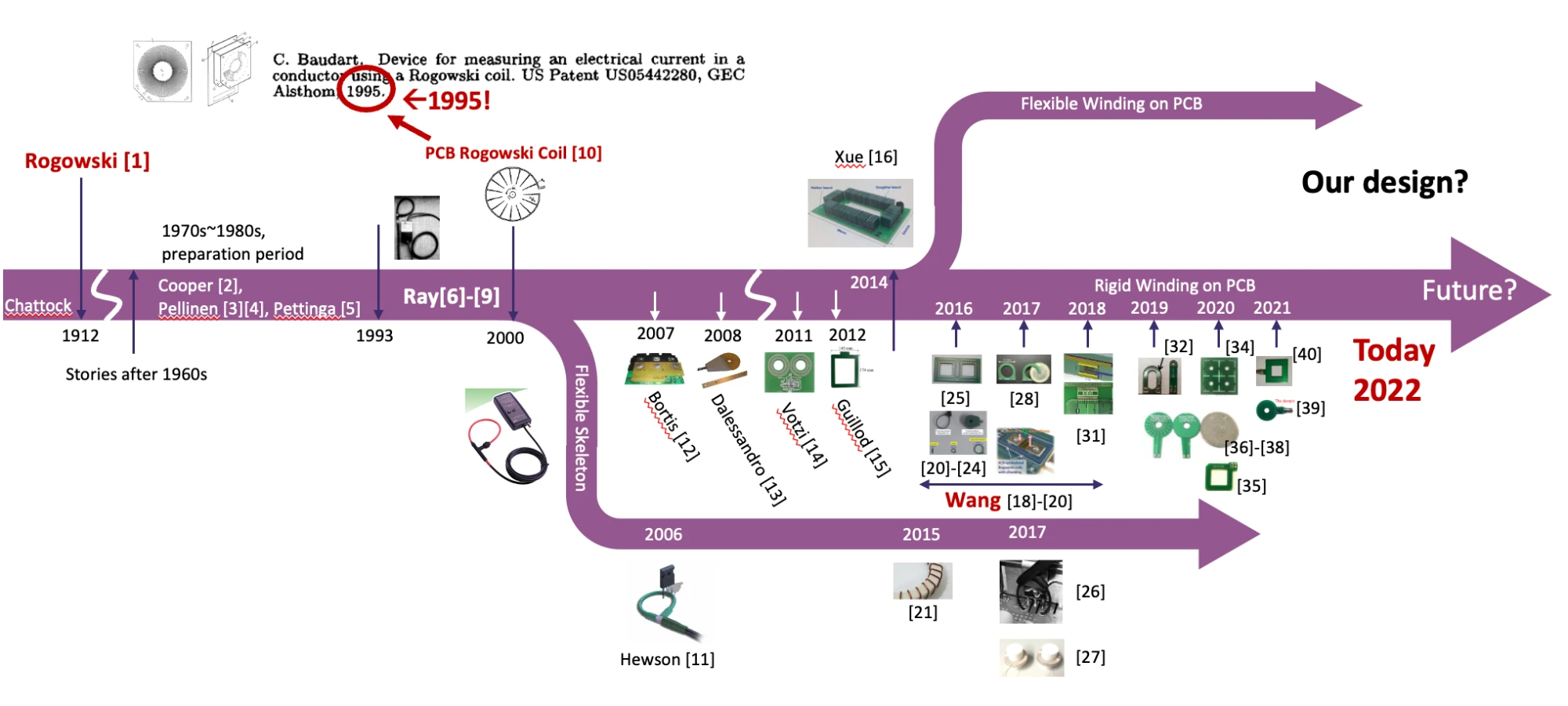
The review, completed in 2022, traced the coil through some 40 publications, from Rogowski’s description of 1912 to coils built into power modules. After a preparation period in the 1970s and 1980s, development followed three paths: coils wound on flexible skeletons, rigid windings on PCB after the first PCB Rogowski coil patent in 1995, and windings on flexible PCB.
Winding Patterns and Their Trade-Offs
On a PCB, the pattern of the turns decides how well the coil rejects current that flows outside it. A coil that responds only to the current through its aperture must close its path completely and must not form loops that link external fields. Koga, Tsukuda, Nakashima and Omura compared four patterns built on four-layer boards, using 9 mm coils whose main winding runs on the outer layers and through-holes (Koga et al., 2016).
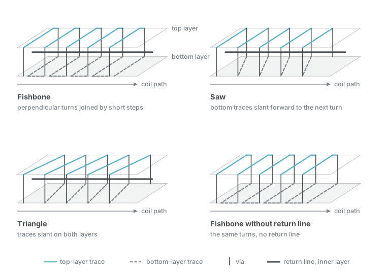
| Pattern | Construction | Trade-off | Maximum error from an outside current |
|---|---|---|---|
| Fishbone | Each turn stands perpendicular to the coil path, with short steps between turns and a return line | Removes unwanted flux paths as far as the PCB process allows; its rejection improves as trace and via pitch shrink | 7% |
| Saw | Traces on one layer cross the path at right angles; traces on the other slant forward to the next turn | Simple to route, and lowest error on one scan path (4%), but the slanted traces leave flux paths that external fields couple into | 10% |
| Triangle | Traces on both layers slant, in opposite directions | Symmetric zigzag, but both slanted layers open the largest unwanted flux paths | 26% |
| Fishbone without return line | Fishbone turns, no return line | Simplest routing, but the winding’s advance around the aperture forms a single loop that links external fields | 218% |
The error is the signal from a current outside the coil relative to the same current through the aperture centre, the maximum over four scan paths. Two lessons follow: a return line is essential, and among patterns with one, the fishbone keeps the turns closest to ideal and rejects outside current best.
Coil Designs
Five PCB coils, designed in July 2024 from the review, vary one feature at a time: the winding pattern, the return line and the outline. Types 1 and 2 use the saw (sawtooth) pattern on a circular outline, without and with a return line. Types 3 and 4 use the fishbone pattern on a square outline, without and with a return line. Type 5 adds a cutout from the aperture to the board edge, so that the coil can be slid around a conductor that is already in place, in the manner of a clamp-type coil. Each board places its coil beside the same signal-conditioning chain, with amplification and integration stages and coaxial connectors for the raw coil output and the final output, so the coils can be compared with identical electronics.
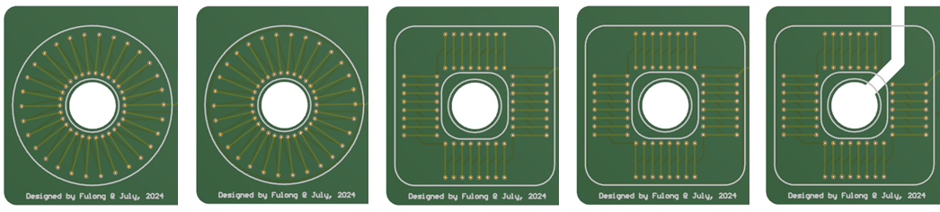
| Type 1 | Type 2 | Type 3 | Type 4 | Type 5 | |
|---|---|---|---|---|---|
| Pattern | Saw | Saw | Fishbone | Fishbone | Fishbone |
| Return line | No | Yes | No | Yes | Yes |
| Outline | Circular | Circular | Square | Square | Square with cutout |
The complete boards and design files of all five coils are in the PCB Rogowski coil repository.
PCB Current Transformer · Current Sensing · Back to Research