
Power Device Reliability Testing
Reliability testing covers environmental and thermal stress tests of SiC power modules and GaN devices, and complements the electrical and thermal characterisation work.
Why Accelerated Stress Testing
Power devices are expected to operate for many years, so their weaknesses must be revealed in weeks rather than in service. Accelerated stress tests apply conditions harsher than normal operation and monitor the device for drift or failure. Reverse-bias tests hold a device in its blocking state at high temperature, and with high humidity in H3TRB, to expose degradation of the blocking junction, passivation and package. Thermal cycling repeatedly heats and cools a device, stressing the interfaces between materials with different thermal expansion.
SiC Power Module HTRB / H3TRB Test
High-temperature reverse-bias (HTRB) and high-humidity, high-temperature reverse-bias (H3TRB) tests were carried out on SiC power modules.
In both tests, the devices are held off, with each gate shorted to its source, while a DC supply applies a high voltage between drain and source. Each device is usually connected through a series resistor, which limits the current if it fails, and its leakage current is recorded throughout the test. A rising leakage current shows the blocking capability degrading.
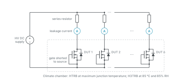
For automotive power modules, the AQG 324 qualification guideline sets these conditions for the two tests:
| AQG 324 condition | HTRB | H3TRB |
|---|---|---|
| Drain–source voltage | At least 80% of the rated maximum | 80 V, or 80% of the rated maximum |
| Temperature | Maximum junction temperature | 85 °C |
| Relative humidity | — | 85% |
| Gate–source voltage | 0 V, or the datasheet minimum if 0 V does not fully block the channel | As for HTRB |
| Duration | At least 1000 h | At least 1000 h |
| Failure criterion | Leakage current rises fivefold | Leakage current rises tenfold |
The 80 V option for H3TRB applies only to devices rated above 100 V. In H3TRB, the voltage is limited so that heat from the leakage current does not dry out the humidity around the device.
GaN Thermal Cycling
GaN devices were tested under repeated thermal cycles.
The devices sit unpowered on a cooling plate whose temperature swings between a minimum and a maximum, dwelling at each extreme long enough for the whole device to reach it. For the GaN devices, a Peltier module under the cooling plate from the thermal-resistance setup sets the temperature. Each cycle stresses the interfaces between the die, its attach and the package, because they expand by different amounts; measuring the devices at intervals, for example their thermal resistance, shows the damage accumulating.
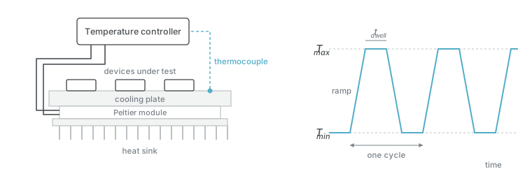
For comparison, AQG 324’s thermal shock test for power modules cycles between −40 °C and +125 °C, with dwells of more than 15 minutes, for at least 1000 cycles, and counts a 20% rise in thermal resistance as a failure.