
Zhejiang University 50 kW DC Microgrid Test Bench
A two-month research secondment at Zhejiang University, from March to April 2018 in Prof. Wuhua Li’s group, centred on operating the group’s 50 kW DC microgrid test bench and on the design principles behind it: converter protection, hierarchical control, passivity-based stabilisation and the control of three-phase AC–DC interface converters. The secondment also provided systematic training in microgrid test-bench design.
The Test Bench
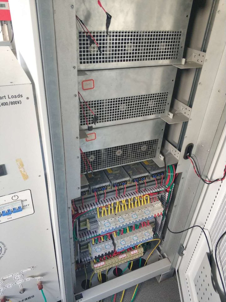
The bench houses its power converters in cabinets. Fan-cooled converter modules sit above the auxiliary power supplies, terminal blocks and protection wiring, and a smart-load cabinet alongside provides controllable loads.
Converter Protection
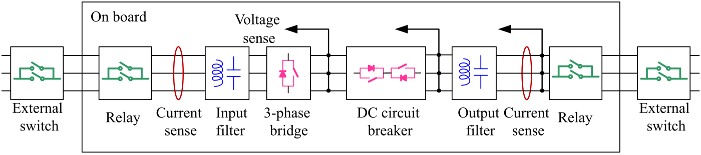
In a system of distributed converters, a single fault can collapse the whole microgrid, so a faulty converter must be isolated immediately. The bench combines hardware relays with software protection, and each converter sits within its own protection chain: external switches and relays at both ports, current sensing on both sides, input and output filters, and a DC circuit breaker after the three-phase bridge, with the DC voltage sensed on both sides of the breaker.
Hierarchical Control
The bench follows a three-layer hierarchical control scheme, which its designers describe as mode-adaptive decentralised control:
| Layer | Control | Function |
|---|---|---|
| Primary | Self-disciplined | Stabilises each converter locally on the basis of passivity theory, with double-loop, droop and voltage feed-forward control |
| Secondary | Self-adaptive | Uses the common DC bus voltage as the signal carrier, so that converters change operating mode without communication links |
| Tertiary | Self-organised | Distributes power over CAN communication according to cost, weather and other conditions, by adjusting the droop coefficients, voltage references and maximum power limits of the lower layers |
The secondary layer applies DC bus signalling, the principle also behind the dual-window DC bus signalling method developed in the PhD research.
Passivity-Based Stabilisation
Passivity is the core of the scheme, because it guarantees stable operation of the interconnected converters. Consider a system with states x ∈ ℝn, inputs u ∈ ℝm and outputs y ∈ ℝm. The map u → y is passive if there exist a storage function H(x), bounded from below, and a non-negative dissipation d(t) ≥ 0 such that
A passive system cannot store more energy than it is supplied, and an interconnection of passive systems remains passive, so a microgrid whose converters all present passive ports to the DC bus remains stable. A storage function for a complete DC microgrid is difficult to find, so the bench applies the idea at each converter instead: voltage feed-forward control shapes each interface converter to satisfy the passivity condition at its port. The same idea underlies the passive stabiliser developed for Boost interface converters in the PhD research.
AC–DC Interface Control
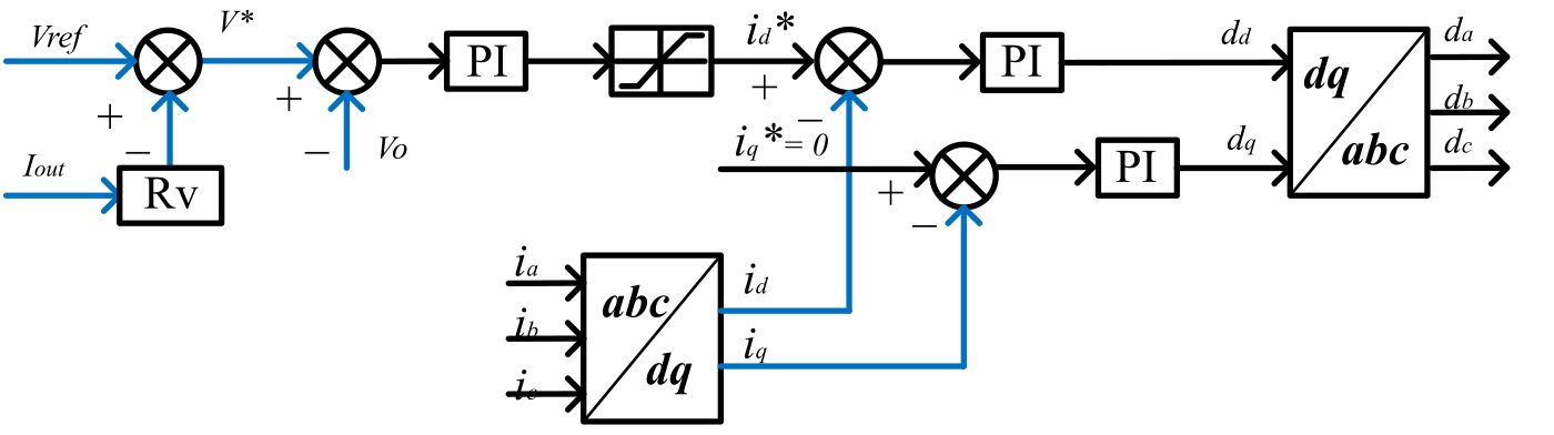
Two three-phase AC–DC interface converters were modelled to study droop control between them. Each regulates its DC output with an outer voltage loop whose reference is drooped by a virtual resistance Rv,
A PI controller turns the voltage error into a limited d-axis current reference id, and the q-axis reference iq is zero for unity power factor. Inner PI loops regulate id and iq, obtained from the phase currents by the abc–dq transformation, and the inverse transformation returns the phase duty cycles.
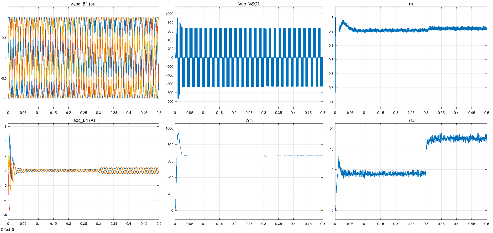
In simulation, the load steps at 0.3 s. The converter’s DC current rises from about 9 A to about 17.5 A, while the DC voltage, regulated near 670 V, falls slightly, as droop control intends; the modulation index rises from about 0.90 to 0.92 to deliver the extra power.
All experimental platforms · DC Microgrid Control Strategies · Back to Research